Water Flow Controller Circuit

In this article we will be discussing the water level indicator circuit which informs you about the different levels of water in the water tank or container.
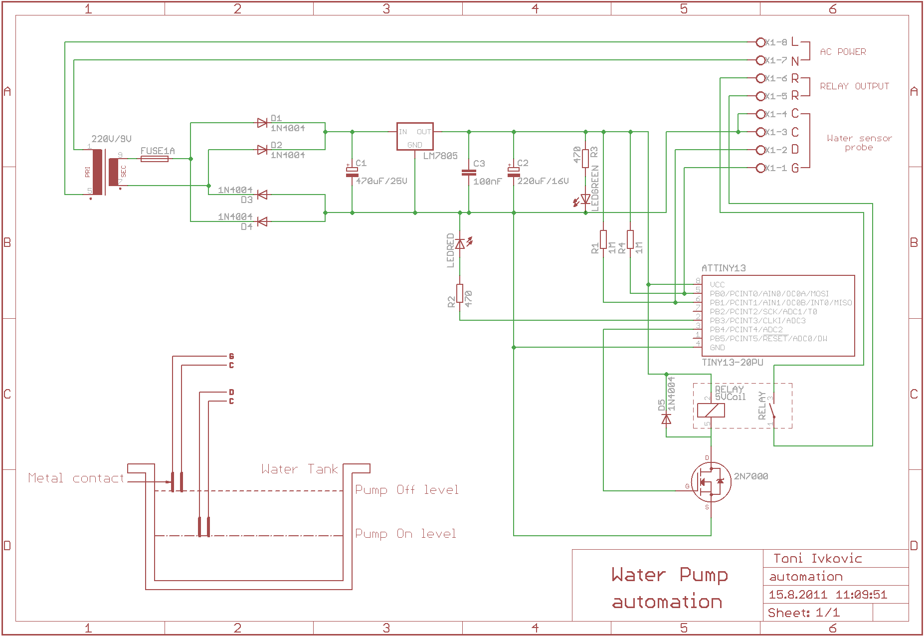
Water flow controller circuit. The circuit formed by transistors q1 and q2 is designed to turn on the red led pump protect whenever there is no water between pump protect electrode and ground electrode at pump reservoir. The idea was requested by mr. We have already discussed this programmable timer circuit in one of my previous posts. Water flow valve timer controller circuit homemade circuit projects the article details about an automatic water flow controller timer circuit which switches a valve mechanism on off as per a set predetermined timing sequence.
The design the proposed water flow controller circuit using a valve timer circuit can be implemented by using a simple two stage programmable timer design as shown in the above diagram. Water tank overflow is a common problem which leads to the wastage of water. Though there are many solutions to it like ball valves which automatically stop the water flow once the tank gets full. In the circuit in figure 10 15 almost 95 of the power used by the system becomes heat.
Q1 base current is too small less than 1 micro amp. If pump is running then the pump running status lamp will be on. This panel contains led s to show the status of the water level control. If the level of the water reaches high point the pump will started so that the water can be drained and thus lowering the level.
When the water level of the tank goes below the low level marked by l the voltage at pin 2 of ic1 becomes low. Q1 comes on as soon as water level drops below pump protect. The connection of the water flow sensor and lcd 16x2 with the arduino is given below in table format. The other hand is placed under the running water to judge measure the temperature.
In any meter in circuit with a fixed volume pump the wasted energy will heat the fluid. The water level controller circuit is a simple mechanism to detect and control the level of water in the overhead tank and also in the other containers. You can also use this device to sense the water level at a determined level. The circuit described here is built around timer ic1 555.
A water pump controller senses the level of water in a tank and drives the water pump. A meter in flow control circuit for an over running load is not the normal design but it may be necessary when the circuit has a pressure switch or a sequence valve. The water flow sensor circuit diagram is shown below to interface a water flow sensor and lcd 16x2 with arduino. It has pump running low level high level signals.
If you are new to arduino and lcds you can consider reading this interfacing arduino and lcd article. The circuit is designed so that the buzzer will start beeping once the water tank is completely full. As a result internal sr flip flop of ic1 resets and its output goes high.


